

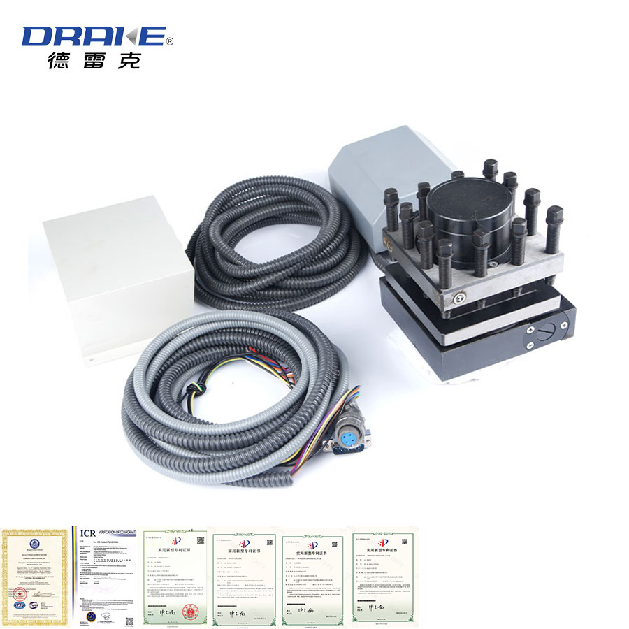
Product Details
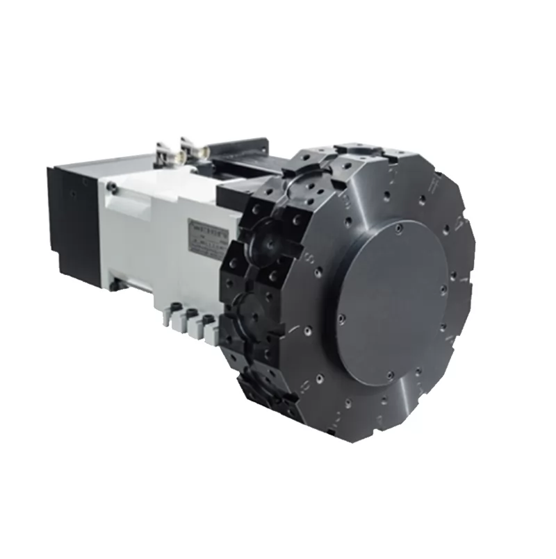
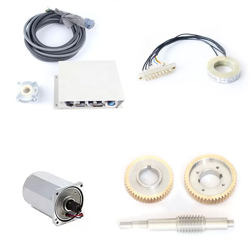
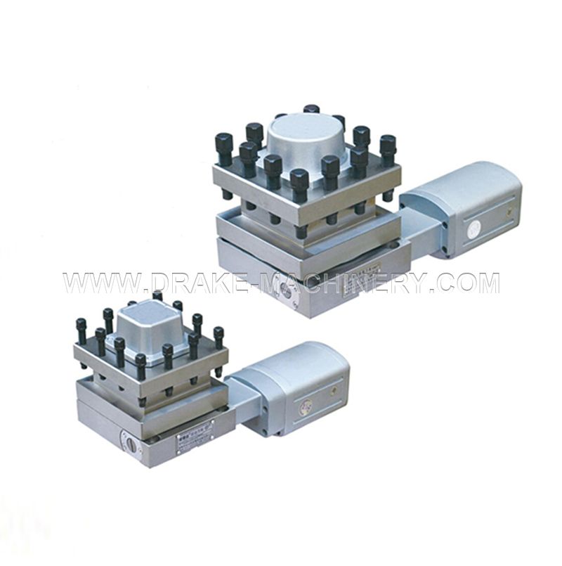
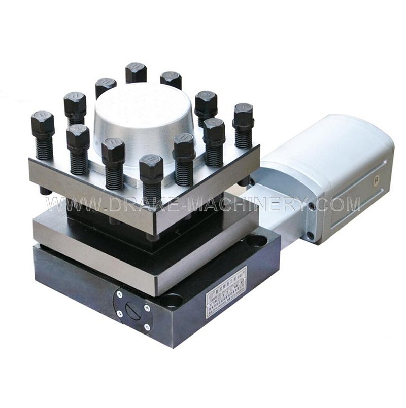
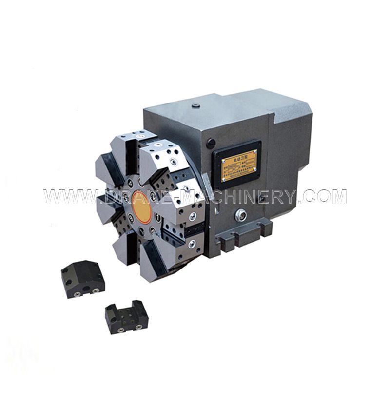
LD4B series vertical NC turret adopts the working principle of worm wheel and worm for driving, 3 pieces face gear coupling as fine indexing mechanism, big screw for clamping,sending signal with Hall unit. It features steady rotating, indexing without tool-holder disk lifting. It is as popular product for NC lathe. The nc turret is an essential component in CNC machining, designed to efficiently hold multiple tools. A 4-station tool turret or quad turret lathe allows quick tool changes during machining. The 4 station automatic tool turret enhances productivity by automating the process. A turret tool post is commonly used in an nc lathe, providing precision in tool positioning. In modern CNC systems, the turret in cnc machine or tool turret in cnc is a crucial element for streamlining operations. Understanding what is turret in cnc machine is key to optimizing machine tool performance.
1. Confirm various parameters when choosing models of turret. Choose the number of stations according to quantity of part procedure and complicacy.
2. Choose tool specifications according to model of machine tool and cutting force. Choose the front type or rear type tool turret according to the cutting directions of the machine tool.
3. After the mounting of boring cutter seat of horizontal turret, Self-bore the inner hole according to the size of boring bar and make a corresponding mark. The tool should be fixed in the former position in the later mounting.
4. The distance tool reaching out of upper housing distance is usually not more than 2/3 upper housing size. Please note when placing an order,if more than the limit.
5. Touch by hand or other things is forbidden when turret is running to avoid injury or damage.
6. If customers have any special requirements or changes in parameters, please offer some data and contact with our company.
Why Choose the 4 station automatic tool turret?
4-Station Automatic Tool Indexing
The 4 station tool turret provides four indexed tool positions, making it suitable for CNC lathes performing common turning operations with a limited but frequently used tool set.
It is particularly suitable where the machining cycle requires automatic switching between tools without using a larger multi-station turret.
Worm Gear Drive for Stable Rotation
The 4 station automatic tool turret uses a worm wheel and worm transmission structure to drive turret rotation. This structure supports controlled indexing between tool positions and is well suited to economical and general-purpose CNC lathe configurations.
Three-Piece Face Gear Precision Indexing
A three-piece face gear coupling is used as the fine indexing mechanism. Together with screw clamping, this helps maintain consistent positioning after each tool change.
No Tool Disk Lifting During Indexing
The 4 station automatic tool turret design indexes without lifting the tool-holder disk, helping simplify the indexing movement and maintain stable turret operation.
Hall Sensor Position Feedback
Tool position signals are transmitted through a Hall sensing unit, allowing the turret position to be integrated with the CNC control sequence.
Drake is a leading enterprise with 15+ years of factory experience, specializing in machine tool accessories and offering OEM & ODM services. We cooperate with over 60 countries and provide one-stop purchasing solutions for for Power Chuck, Collet Chuck, Turret, Tool Holder, Rotary Cylinder, Laser Chuck, Tool magazine, and more. Our strict adherence to international quality standards and comprehensive product range ensures tailored processing solutions for diverse customer needs.
Product Size
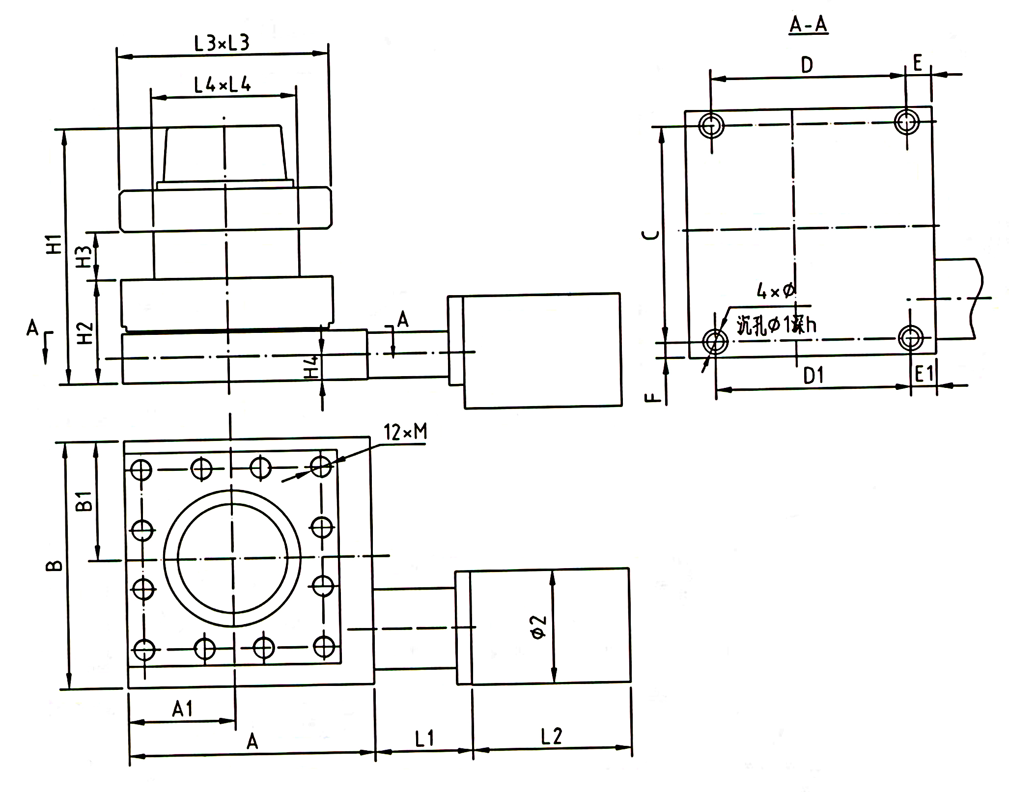
Product Parameters
| Model/Data | Center height(mm) | Motor power (W) | Max.tangential torque(N·m) | Repeatability accuracy(") | Time of changing tool and lock(s) | ||
| 90º | 180º | 270º | |||||
| LD4B-CK0620 | 51 | 50 | 200 | ±2 | 1.5 | 2 | 2.5 |
| LD4B-CK0625 | 51 | 90 | 300 | ±2 | 1.7 | 2.2 | 2.7 |
| LD4B-CK6125 | 57 | 90 | 400 | ±2 | 1.7 | 2.5 | 2.7 |
| LD4B-CK6132 | 70 | 120 | 500 | ±2 | 2 | 2.5 | 3 |
| LD4B-CK6140 | 81 | 120 | 600 | ±2 | 2 | 2.5 | 3 |
| LD4B-CK6150 | 121 | 120 | 600 | ±2 | 2.2 | 2.7 | 3.3 |
| LD4B-CK6163 | 120 | 180 | 800 | ±2 | 2.5 | 3.2 | 3.9 |
| LD4B-CK6172 | 120 | 250 | 1200 | ±2 | 3.7 | 4.7 | 5.7 |
| LD4B-CK6180 | 120 | 250 | 1500 | ±2 | 4.1 | 5.2 | 6.3 |
| LD4B-CK61100 | 145 | 250 | 1900 | ±2 | 4.5 | 5.6 | 6.8 |
| Model/Dim | H1 | H2 | H3 | H4 | L1 | L2 | L3 | L4 | A | A1 | B | B1 |
| LD4B-CK0620 | 146 | 51 | 26 | 15.5 | 60 | 100 | 100 | 72 | 114 | 50 | 114 | 50 |
| LD4B-CK0625 | 152 | 51 | 30 | 17 | 78/114 | 118 | 130 | 99 | 130 | 65 | 138 | 65 |
| LD4B-CK6125 | 159 | 57 | 31 | 16.5 | 78/114 | 118 | 136 | 104 | 136 | 68 | 148 | 68 |
| LD4B-CK6132 | 187 | 70 | 40 | 20 | 76 | 128 | 158 | 114 | 161 | 79 | 171 | 79 |
| LD4B-CK6140 | 200 | 81 | 38 | 19.5 | 76 | 128 | 166 | 116 | 192 | 83 | 192 | 93 |
| LD4B-CK6150 | 240 | 121 | 38 | 37 | 76 | 128 | 166 | 116 | 192 | 83 | 192 | 93 |
| LD4B-CK6163 | 234 | 120 | 42 | 31 | 110 | 132 | 200 | 120 | 200 | 100 | 200 | 100 |
| LD4B-CK6172 | 255 | 120 | 50 | 30 | 103 | 140 | 240 | 160 | 240 | 120 | 240 | 120 |
| LD4B-CK6180 | 245 | 120 | 55 | 25 | 103 | 140 | 280 | 200 | 280 | 140 | 280 | 140 |
| LD4B-CK61100 | 285 | 145 | 65 | 30 | 103 | 140 | 300 | 192 | 300 | 150 | 300 | 150 |
| Model/Dim | C | D | D1 | E | E1 | F | φ | φ1 | φ2 | h | M |
| LD4B-CK0620 | 100 | 100 | 70 | 7 | 18 | 7 | φ7 | φ11 | φ78 | 6.5 | M8 |
| LD4B-CK0625 | 120 | 100 | 90 | 15 | 20 | 9 | φ9 | φ14 | φ88 | 10.5 | M10 |
| LD4B-CK6125 | 126 | 108 | 108 | 14 | 14 | 11 | φ11 | φ17 | φ88 | 11 | M10 |
| LD4B-CK6132 | 146 | 126 | 126 | 23 | 23 | 12 | φ13 | φ19 | φ88 | 13 | M16 |
| LD4B-CK6140 | 168 | 152 | 152 | 20 | 20 | 12 | φ13 | φ19 | φ88 | 13 | M16 |
| LD4B-CK6150 | 168 | 152 | 152 | 20 | 20 | 12 | φ13 | φ19 | φ88 | 13 | M16 |
| LD4B-CK6163 | 177 | 150 | 130 | 25 | 35 | 11.5 | φ13 | φ19 | φ98 | 13 | M16 |
| LD4B-CK6172 | 210 | 210 | 160 | 15 | 40 | 15 | φ18 | φ27 | φ98 | 17 | M16 |
| LD4B-CK6180 | 240 | 240 | 240 | 20 | 20 | 20 | φ18 | φ27 | φ98 | 17 | M16 |
| LD4B-CK61100 | 260 | 260 | 260 | 20 | 20 | 20 | φ18 | φ27 | φ98 | 17 | M16 |
4 station automatic tool turret Selection Guide
| Model | Center Height | Motor Power | Max. Tangential Torque | Best Selection Direction |
|---|---|---|---|---|
| LD4B-CK0620 | 51 mm | 50 W | 200 N·m | Compact CNC lathe |
| LD4B-CK0625 | 51 mm | 90 W | 300 N·m | Small CNC lathe |
| LD4B-CK6125 | 57 mm | 90 W | 400 N·m | Small to medium lathe |
| LD4B-CK6132 | 70 mm | 120 W | 500 N·m | Medium CNC lathe |
| LD4B-CK6140 | 81 mm | 120 W | 600 N·m | Medium CNC lathe |
| LD4B-CK6150 | 121 mm | 120 W | 600 N·m | Larger center-height requirement |
| LD4B-CK6163 | 120 mm | 180 W | 800 N·m | Higher cutting load |
| LD4B-CK6172 | 120 mm | 250 W | 1200 N·m | Heavy turning requirement |
| LD4B-CK6180 | 120 mm | 250 W | 1500 N·m | Higher torque requirement |
| LD4B-CK61100 | 145 mm | 250 W | 1900 N·m | Large CNC lathe configuration |
How to Select the Correct 4 station CNC turret
1. Confirm the Turret Center Height
Center height is one of the first parameters that should be matched with the CNC lathe structure.
The LD4B range currently covers:
51 / 57 / 70 / 81 / 120 / 121 / 145 mm
Do not choose a turret only according to the nominal lathe model. Confirm the actual installation dimensions before ordering.
2. Check Required Cutting Torque
For heavier turning, larger tools or higher cutting forces, select a model with sufficient tangential torque.
The LD4B series ranges from 200 N·m to 1900 N·m, so the required cutting load should be considered together with machine size.
3. Confirm Front or Rear Turret Installation
The correct turret orientation depends on the cutting direction and machine layout. Drake's existing technical guidance also recommends confirming whether a front-type or rear-type turret is required according to the machine tool configuration.
4. Check Mounting Dimensions
The current LD4B range has different values for:
H1–H4
L1–L4
A / A1
B / B1
C / D / D1
Mounting hole diameters
Thread specifications
For replacement projects, these dimensions are often more important than simply matching the model name.
5. Confirm Tool Overhang
Drake's current technical instruction recommends that the tool extension beyond the upper housing generally should not exceed approximately two-thirds of the upper housing dimension. If the application requires a longer overhang, this should be confirmed before ordering.
LD4B vs LD4: Which Should I Choose?
| LD4B | LD4 | |
|---|---|---|
| Stations | 4 | 4 |
| Drive Principle | Worm wheel & worm | Worm wheel & worm |
| Indexing | Three-piece face gear coupling | Face gear coupling |
| Main Selection Focus | Multiple size and torque configurations | Economic CNC lathe applications |
| Recommended Approach | Select by center height, torque and mounting dimensions | Select according to machine configuration |
Need help comparing LD4B and LD4? Send your machine specifications and we can help identify the more suitable series.
Replacing an Existing 4 Station CNC Turret?
To reduce dimensional mismatch during replacement, please send:
Existing turret model
CNC lathe brand and model
Turret center height
Mounting dimensions
Voltage and electrical requirements
Front or rear mounting position
Existing turret nameplate photo
Top, side and mounting-base photos
Required cutting torque, if known
If the original model plate is unclear, send clear photos and key dimensions instead.
Send Your Turret Photos for Matching
-
Precautions when using a hydraulic center frame.
Aug. 28, 2026
-
How to install the top cover of the hydraulic center frame?
Aug. 28, 2026
-
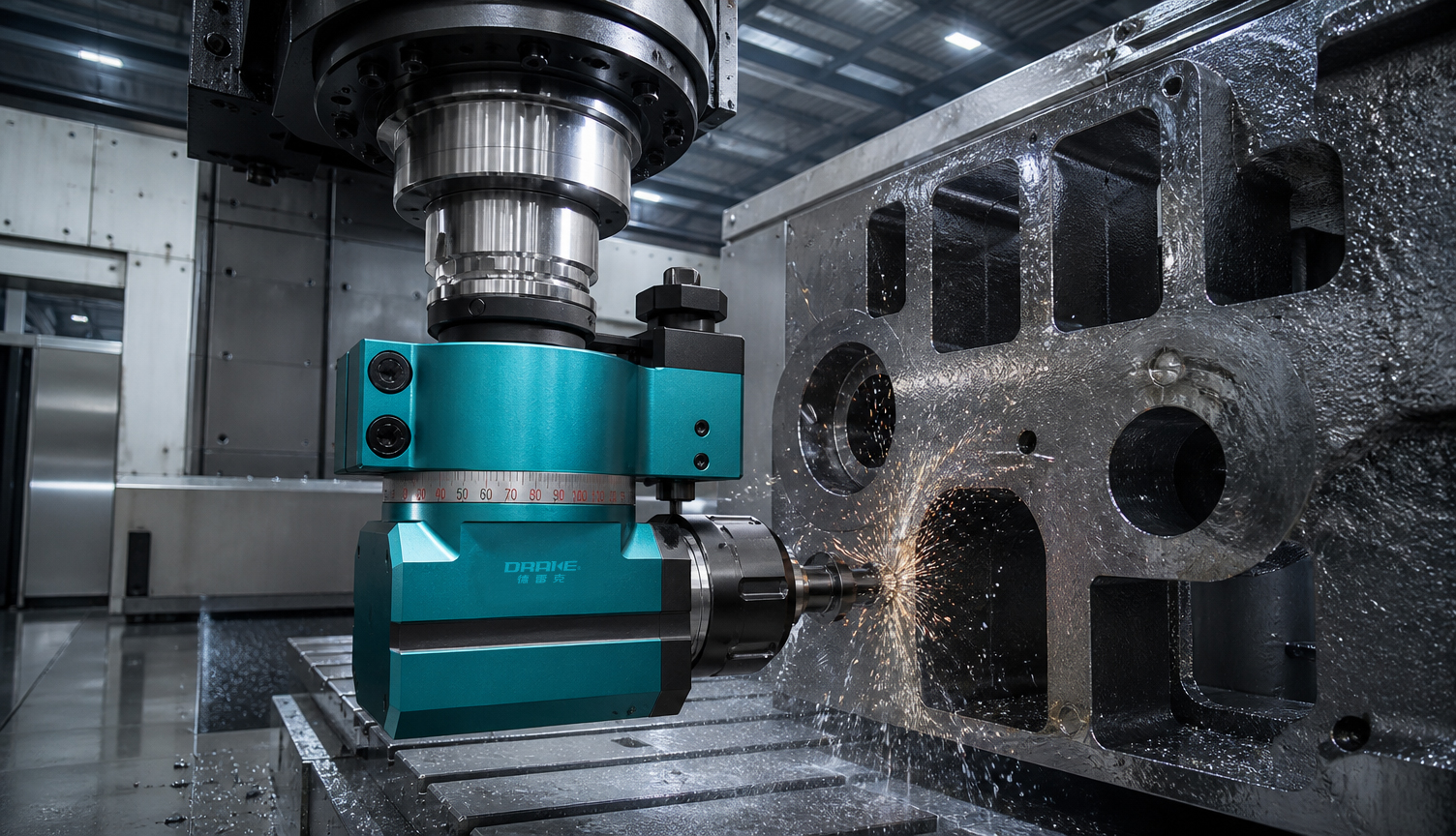
What to Pay Attention to When Using Angle Heads and Side Milling Heads
Aug. 27, 2026
-
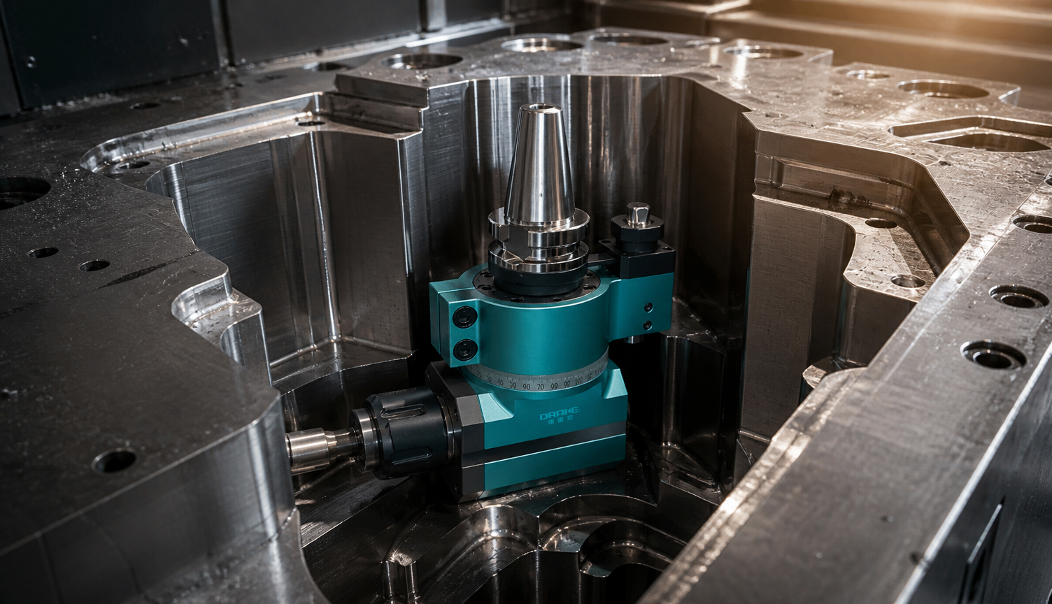
What is an angle head? What are the applications and classifications of angle heads?
Aug. 27, 2026
-
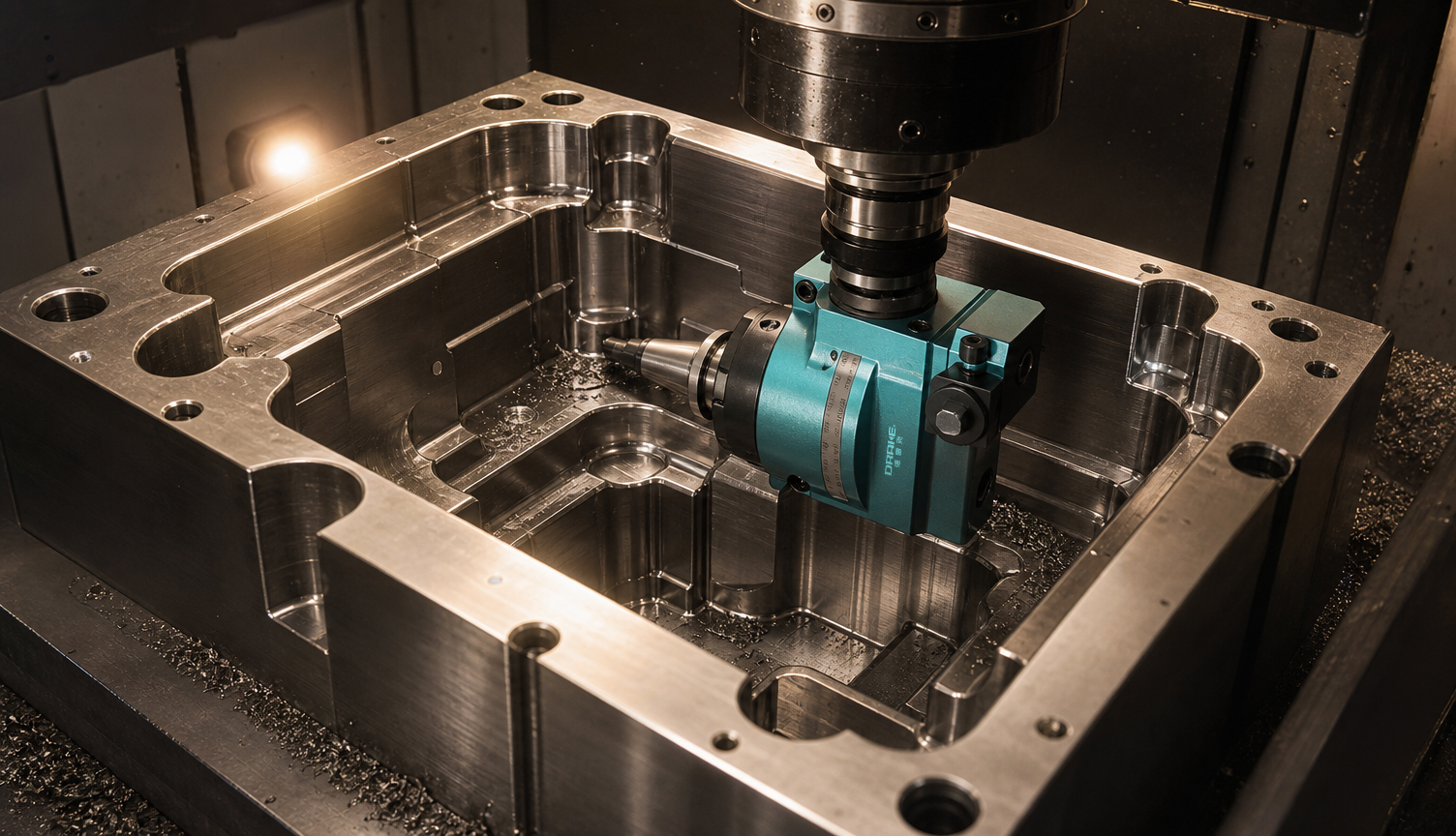
What are the standards for purchasing angle heads?
Aug. 27, 2026