
Aug. 28, 2026
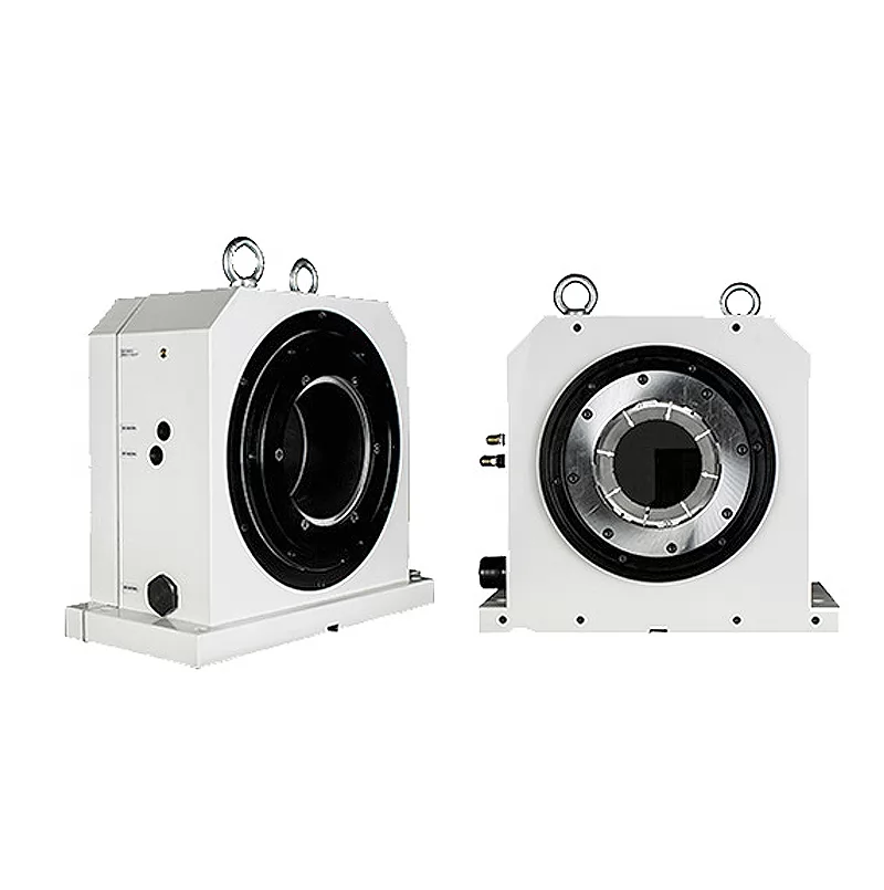
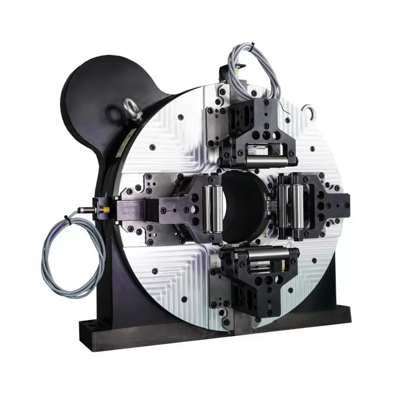
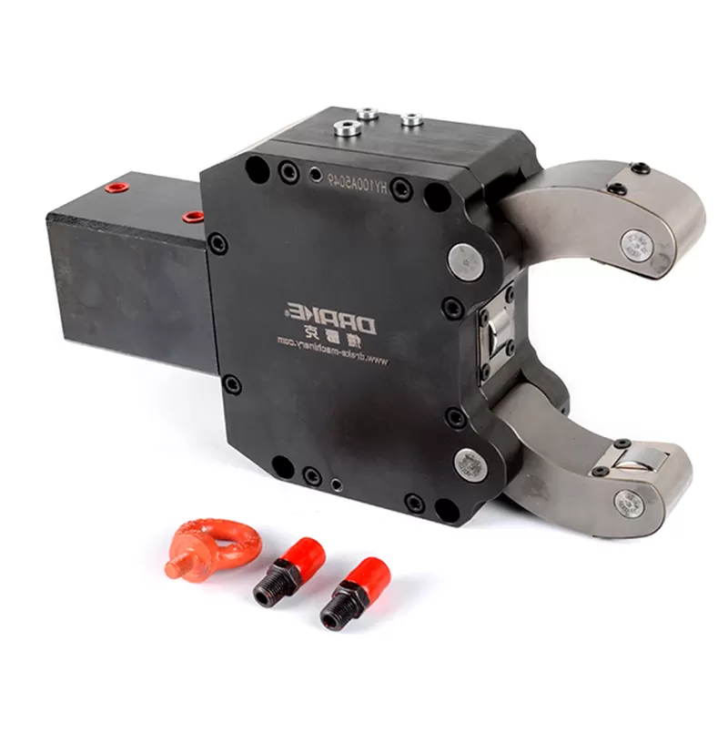
When machining long shaft parts on CNC machine tools, a hydraulic center rest is generally required to support the entire process.
The three support rollers of the hydraulic center rest are reciprocated by a plate cam, enabling the clamping and releasing of the workpiece.
The positioning accuracy of the CNC center rest primarily depends on the machining accuracy of the plate cam curve.
The circles formed by the three pressure rollers supporting the machined shaft must be concentric with the spindle.
Pressure roller one's movement is directly propelled by a hydraulic cylinder, which in turn moves the plate cam forward.
The cam drives the cam roller on the left end of the lever, causing pressure rollers two and three to feed through the lever fulcrum.
The circles formed by the three pressure rollers at each point are concentric with the machine tool spindle center.
Therefore, the positioning accuracy of the hydraulic center rest depends on the plate cam curve equation and manufacturing accuracy.
To ensure that the machining of parts is within the acceptable error range, the hydraulic center rest increases the rigidity of the parts and improves machining accuracy.
The system offers advantages such as stable spindle rotation, stable tool post, smooth feed speed, adjustable taper, high trajectory accuracy, and high machining efficiency.
With a high degree of automation, machining steps can be programmed into the entire machining process according to detailed machining content and sequence, achieving programmed automatic machining.
The hydraulic center support is fixed behind the machine bed. While the workpiece is rotating,
the two lower support jaws are brought into even contact with the workpiece support surface and locked.
The top cover is then tightened, and the position of the upper support jaws is adjusted and locked.
The support jaws apply force evenly, with appropriate tightness, ensuring smooth and natural movement.
When using workpiece surfaces with high clamping precision, to prevent wear on the workpiece surface from the support jaws,
a layer of pure copper sheet or fine sandpaper is placed between each support jaw and the support surface, with the back of the sandpaper attached to the workpiece surface.
When the workpiece surface has keyways or notches, a brass collar is used on the outer surface of the workpiece to serve as the hydraulic center support surface.