Jun. 23, 2025
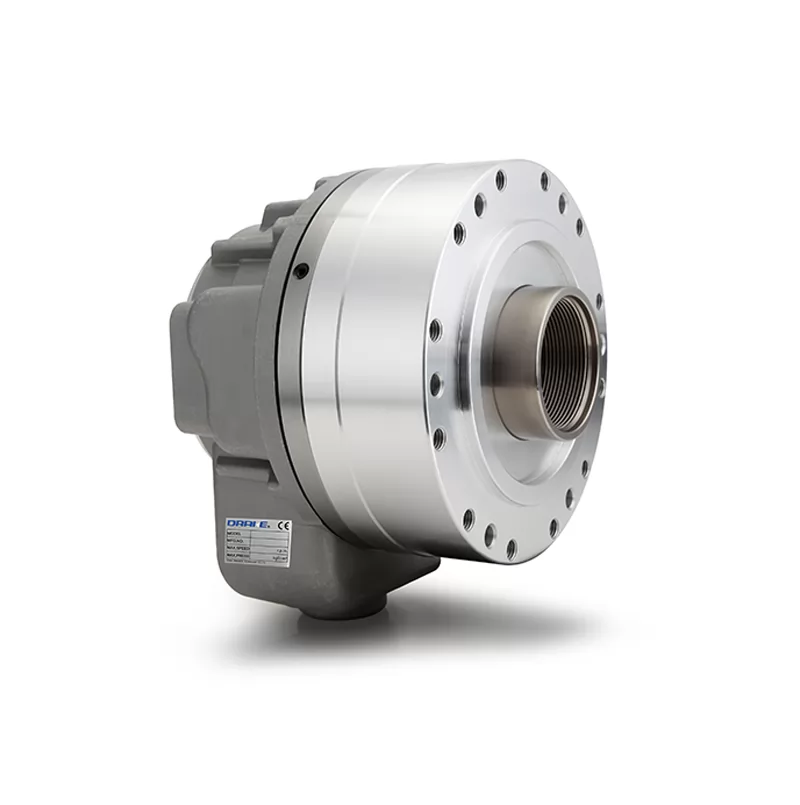
Pneumatic chuck is a mechanical device used to clamp workpieces on machine tools.
The most common one is manual chuck. However, with the development of technology, pneumatic chuck, hydraulic chuck and electric chuck have appeared.
These chucks also have their own advantages and powerful functions.
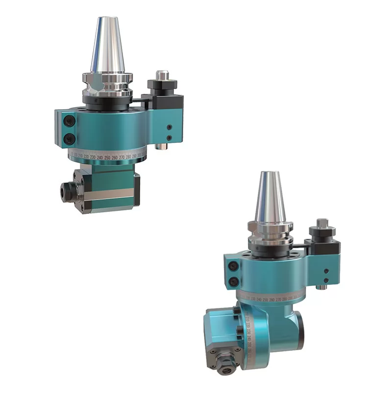
Working principle of pneumatic chuck
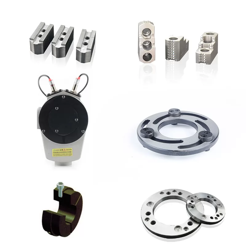
Main working accessories of chuck: inlet air pipe, air distribution switch, exhaust port, airway, airway connector,
rolling bearing, cylinder bearing, piston, pull rod, lathe spindle, short arm, claw, long arm.
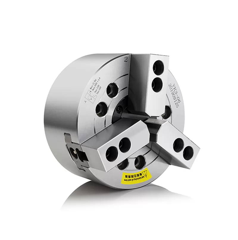
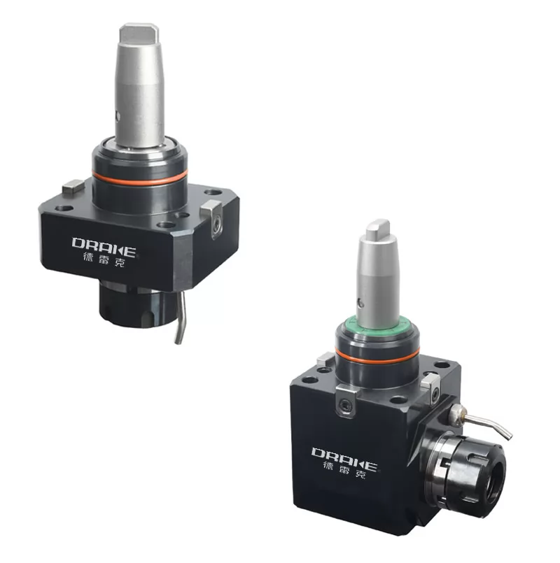
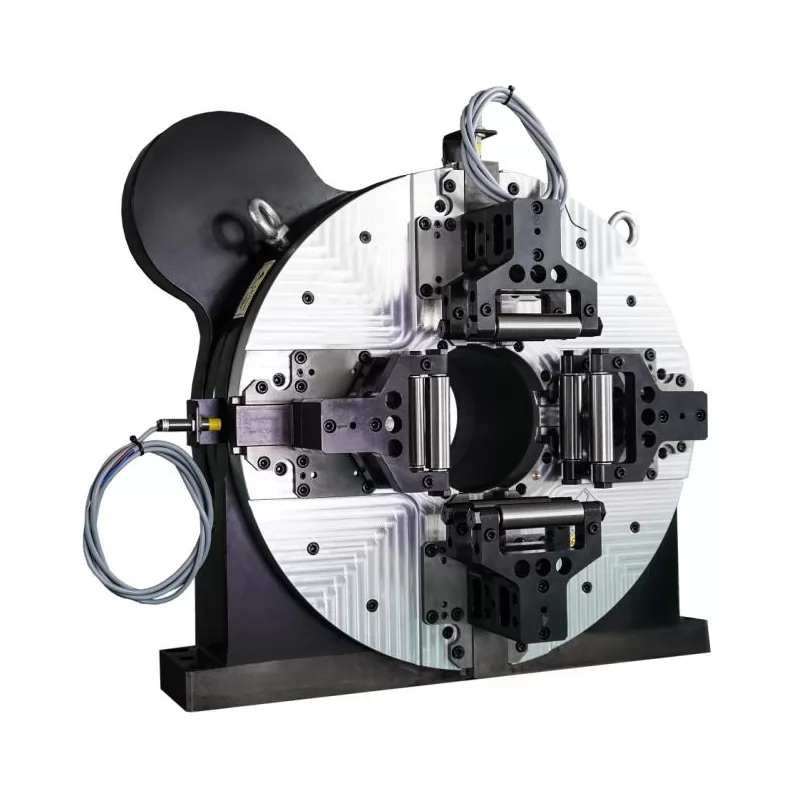
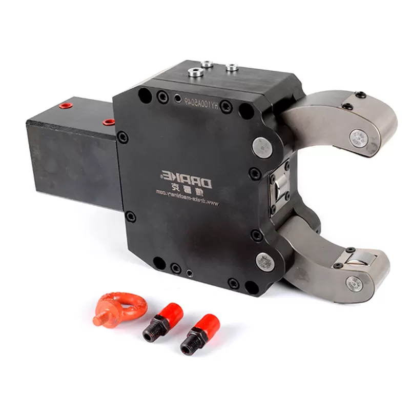
The thing called "air claw" in pneumatic chuck is the main working part. There are many types of air claws, from two claws to four claws.
The power source of air claw comes from the cylinder. The cylinder is used to compress air. When the air is squeezed, it will push the piston.
The action of tightening and releasing the pneumatic chuck is completed by the intensification and release of the air.
Repeatedly, the working state of the pneumatic chuck in our eyes appears.
1. Check whether the chuck connection flange is aligned with the connection step on the back of the chuck;
2. Check whether the inner hole of the connection sleeve matches the outer diameter of the spindle at the tail of the machine tool;
3. Clean the debris in the spindle hole;
4. First install the connection sleeve on the outer diameter of the spindle at the tail of the machine tool,
and calibrate it with a dial base and a dial indicator before and after tightening.
The runout of the radial outer diameter and the axial end face should be less than 0.03mm;

5. Clean the chuck and the connecting flange, put the clamp on the telescopic rubber hose and insert it into the two air source plugs on the back of the chuck,
then clamp it with pliers (just clamp the protruding part inwards), arrange the tube smoothly (the tube should not be bent), and you can use tape to wrap it in sections;
6. Put the chuck with the air pipe inserted next to the machine tool connecting flange (you can use a wooden board to raise it to parallel with the flange),
then use a pulling object to pull the tube (through the spindle hole) to the tail of the shaft, and move the chuck to the connecting flange while pulling the tube,
and tighten the chuck through the connecting hole on the flange. Fixed on the flange;
7. Pull the pipe outward as far as possible (you will feel resistance on your hand and the pipe is almost straightened at this time),
wrap the pipe with tape around the spindle hole and block it with a screwdriver or other object to prevent the pipe from rebounding directly into the spindle hole after you release your hand,
then cut off the excess pipe 100-150 mm away from the hole, blow air into the two pipes respectively,
check which one is clamping and which one is loosening, mark the clamping pipe with a marker as No. 1 and the other as No. 2,
or you can mark it in advance when pulling out the air pipe;
8. Put the two air pipes on the clamps and insert them into the plug of the air pressure controller and clamp the clamps with pliers.
When inserting, please align No. 1 with No. 1 and No. 2 with No. 2. Then remove the objects blocking the main shaft hole.
At this time, the pipe will bounce into the main shaft hole. Tighten the left-hand nut on the air pressure controller on the connecting sleeve.
Use iron sheets or brazing wires to fix the anti-rotation bolts on the air pressure controller to the equipment body to prevent it from rotating due to the rotation of the main shaft. 9.
Install the electric control board in a hidden place of the equipment (to prevent collision during work), and connect the power supply to AC220 V,
insert the connecting air pipes into each plug respectively, the one on the left end of the air pressure controller is No. 1, the one in the middle is No. 2,
the one below the electric control board is No. 1, and the one above is No. 2, then remove the oil container next to the pressure gauge and add clean No. 46 lubricating oil (80% full),
pull the total air supply and insert it into the left end socket on the electric control board (next to the pressure gauge), and then adjust the operating pressure according to the processing requirements;
10. When adjusting the pressure, lift the black knob above the pressure gauge upwards, clockwise to increase the pressure,
and vice versa to reduce the pressure. After the adjustment is completed, press the knob down to reset.
 CO.,LTD.")