
Oct. 29, 2026
To choose a CNC Power Chuck for heavy cutting, compare required clamping force, rated speed, jaw configuration, and spindle interface—not just chuck diameter. This guide explains how to choose a CNC power chuck, evaluate a high-torque CNC lathe chuck, and plan a heavy-cutting workholding setup. Workholding rigidity, turning chuck setup, and jaw mass matter because drawbar force, centrifugal force, and jaw stroke affect how securely a part is held as spindle speed and cutting load change.
A chuck that grips well at a standstill may not provide the same effective grip at operating speed. The practical goal is to hold the part securely through the full cut without exceeding the chuck, machine, jaw, or workpiece limits. DRAKE or any other supplier should be asked for the exact model’s documented ratings and installation requirements; do not infer performance from brand or chuck size alone.

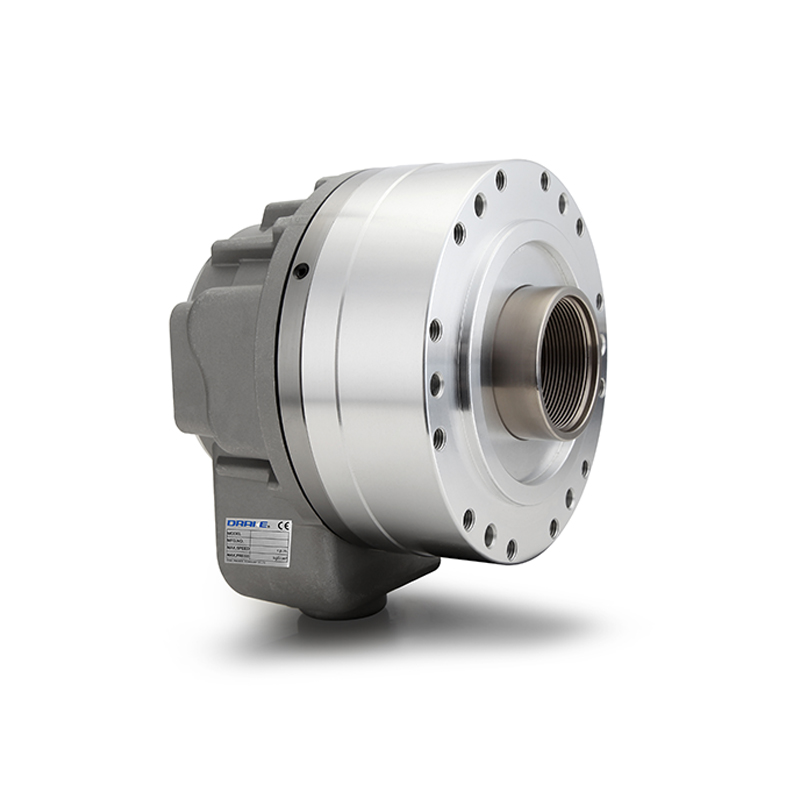
A CNC power chuck converts machine actuator force—typically delivered through a drawtube or drawbar—into radial jaw force. During cutting, the chuck must resist forces that could rotate, shift, or pull the workpiece out of position. The required capacity depends on the workpiece material and geometry, the cutting operation, tool engagement, jaw contact, and spindle speed.
Speed is a critical part of selection. Jaw mass creates centrifugal effects that increase with the square of rotational speed: if speed doubles, the centrifugal effect increases by a factor of four, all else being equal. Consequently, a chuck’s stationary clamping-force figure is not, by itself, proof that the work will be secure at the intended rpm. Use the manufacturer’s speed-versus-clamping-force data for the exact chuck and jaw arrangement.
There is no single chuck size, clamping-force value, or safety factor that is correct for every heavy-cutting job. The machine builder’s limits, chuck documentation, jaw configuration, workpiece condition, and cutting-force calculation all matter.
Do not use hydraulic pressure as a substitute for clamping-force data. The relationship depends on the actuator, draw mechanism, chuck linkage, lubrication, and condition of the components. Use the maker’s specified measurement method.
Tools: Process plan, material data, machine power data, and a cutting-force calculator or engineering calculation. Action: Document the planned cut and estimate the cutting forces for the operation. If using spindle power and cutting speed to estimate tangential cutting force, treat the result as an estimate and account for power losses and the actual cutting condition; do not treat it as the chuck’s required clamping force. Assess the tendency of the part to slip, rotate, or move axially, and check whether the jaws could crush or distort it. Parameters: Use the actual workpiece dimensions, material, tool, feed, depth of cut, cutting speed, and cut direction. Check: Confirm that the process engineer or chuck maker can review the load assumptions and the proposed grip arrangement. If it fails: If cutting data or grip calculations are uncertain, reduce the planned cut for a controlled trial or obtain an engineering review; do not compensate by arbitrarily increasing pressure beyond the chuck or workpiece limits.
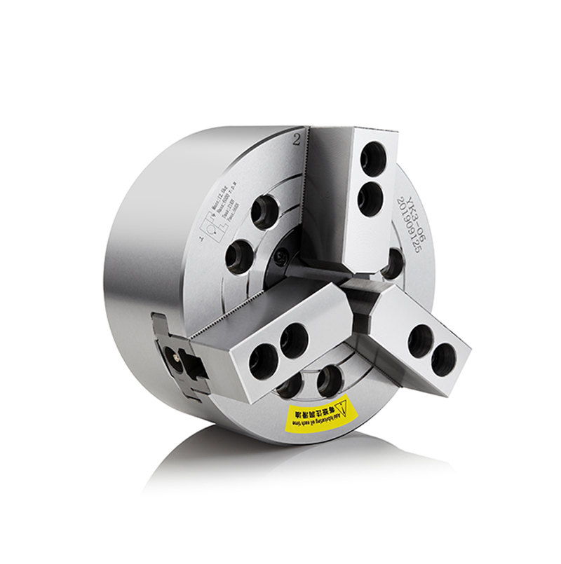
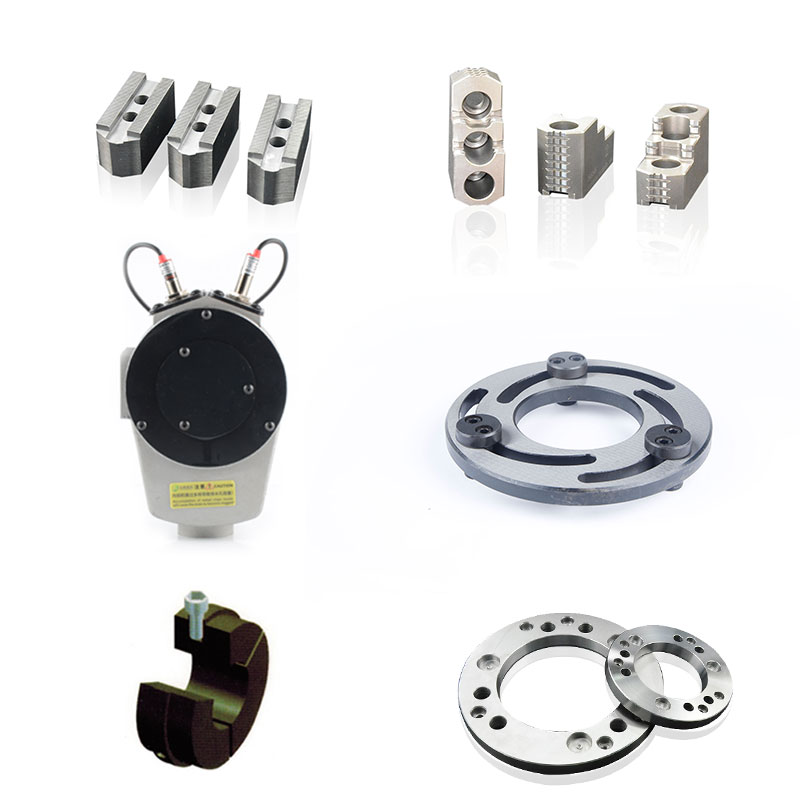
Tools: Part drawing, chuck catalog, jaw drawings, and a dimensional measuring tool. Action: Compare a standard three-jaw arrangement for round parts with alternatives such as four-jaw, two-jaw, or special jaws where the part shape, eccentricity, or contact requirements call for them. Choose through-hole or solid-body construction based on bar capacity and the part-loading method. Confirm that the selected jaws provide adequate contact without interfering with the tool, turret, tailstock, or fixture. Parameters: Check chuck diameter, jaw travel, usable gripping diameter, jaw height and mass, workpiece engagement length, and the maker’s permitted jaw configuration. Check: Confirm the jaws seat correctly and grip the intended surface over the required contact area. If it fails: If standard jaws cannot contact the part reliably, specify suitable soft or special jaws and have their machining, balance, and speed limits reviewed rather than extending the jaws beyond their approved range.
Tools: Manufacturer’s clamping-force chart, chuck manual, and the specified force-measuring equipment. Action: Check the force available at the planned rpm with the exact jaw type and jaw position. Account for jaw mass and any custom jaw modifications. Parameters: Compare the required grip with the maker’s documented force at the intended speed and actuator condition; also observe the maximum speed, maximum draw force, and maximum operating pressure listed for the exact model. Check: Verify that the chuck, jaws, actuator, and machine all permit the planned operating point. If it fails: Lower the spindle speed, revise the jaw design, select a chuck with documented capacity for the duty, or revise the cutting plan. Never exceed a published speed or force rating to make the numbers work.
Tools: Lathe manual, spindle-nose drawing, chuck mounting drawing, and actuator specifications. Action: Match the chuck mounting interface and dimensions to the spindle, and confirm that the drawtube or drawbar connection suits the machine. Verify through-hole clearance if bar work is required. Parameters: Check the spindle-nose standard, mounting dimensions, pilot and register, bolt pattern, thread or adapter details, drawtube connection, stroke, and available actuation force. Check: Confirm that the chuck maker and machine documentation agree on the interface and permitted actuator range. If it fails: Use only an engineered, approved adapter or select a compatible chuck. Do not modify mounting parts or force an incompatible connection into place.
Tools: Cleaning supplies approved for the equipment, inspection light, appropriate measuring tools, and the chuck maker’s maintenance procedure. Action: Clean the mounting register and jaw guides. Inspect for chips, damage, corrosion, cracked jaws, worn serrations, loose fasteners, and evidence of poor lubrication. Parameters: Use the maker’s limits for wear, lubrication, jaw engagement, bolt torque, and service intervals; there is no universal wear limit for every chuck. Check: Confirm smooth, even jaw movement and correct engagement before mounting a workpiece. If it fails: Stop and service or replace affected parts according to the manual. Do not run a chuck with damaged jaws, uncertain engagement, or unexplained movement.
Tools: Rated lifting equipment, specified mounting hardware, torque tools, dial indicator, and the prescribed clamp-force measuring method. Action: Mount the chuck according to the machine and chuck instructions. Seat and secure it correctly, connect the actuator, and confirm the specified drawbar stroke and pressure or force. Grip a representative workpiece or test piece using the approved procedure. Parameters: Apply only the specified mounting torque and actuator settings. Check runout at the location and tolerance required by the part drawing or process plan. Check: Confirm secure jaw engagement, acceptable runout, repeatable clamping, and no abnormal leakage, vibration, or movement. If it fails: Stop the setup, clean and reseat interfaces, inspect the jaws and mounting, and repeat the check. If runout or force remains outside the documented requirement, involve maintenance or the chuck supplier before cutting.
Tools: Machine guarding, the approved setup sheet, and the normal machine monitoring and inspection equipment. Action: Clear the work area, close guarding, and follow the machine and chuck maker’s run-up procedure. Begin with the approved setup speed and a conservative cut, then increase only within documented limits and the validated process plan. Parameters: Keep spindle speed, drawbar force, cutting load, jaw position, and workpiece projection within their verified limits. Check: Watch for vibration, slippage, unusual noise, changing runout, or a part shifting; inspect the first part and verify dimensions. If it fails: Stop the spindle safely, follow lockout and inspection procedures, identify the cause, and correct the setup before resuming. Never reach into a rotating machine or attempt to retighten a running chuck.
No named customer story or measured production result is included here because a customer source and independently verifiable before-and-after data were not provided. Presenting an invented shop-floor anecdote as fact would be misleading. The practical scenario addressed by this guide is a common selection problem: a shop planning a heavier cut must verify that the workpiece, jaws, actuator, chuck, and spindle can safely support the intended load and speed. For a genuine case study, ask the supplier for a documented application with the chuck model, jaw setup, material, operating speed, measured force, and test conditions.
For heavy cutting, select a CNC power chuck from the job requirements outward: calculate or review cutting loads, choose a suitable jaw and chuck arrangement, verify clamping force at operating speed, and confirm spindle and actuator compatibility. Inspect and measure the installed setup, then validate it under controlled conditions. Ask DRAKE or another supplier for model-specific drawings, force-versus-speed data, jaw limits, and maintenance instructions. If these details are unavailable, do not guess: reduce the process demand or obtain technical review before running the job.
Previous: None
Next: Hydraulic Collet Chuck vs Pneumatic Collet Chuck: Key Differences