
Sep. 24, 2026
Turret Disassembly Steps
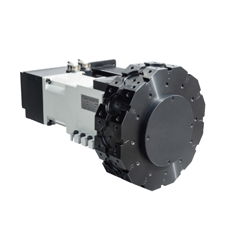
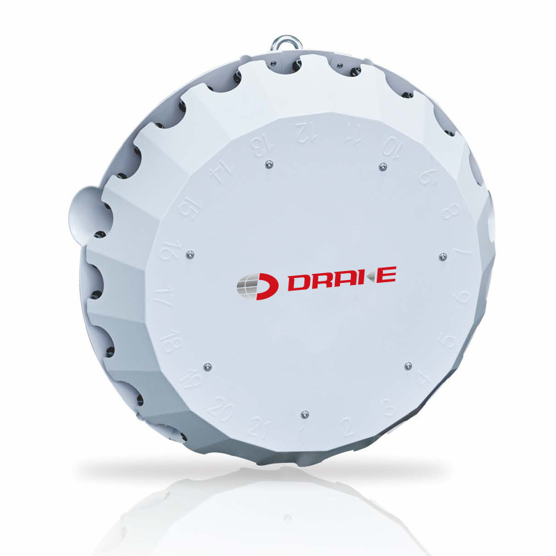
1. Remove the bottom tool disk (secured by six M6 screws). Note: The tool disk is heavy; exercise caution when removing it.
2. Once the tool disk is removed, the coolant outlet block is exposed. Remove the three M5 screws securing the block and take it off; note the orientation of the coolant outlet to ensure it is installed the same way later.
3. After removing the coolant outlet block, the bearing carrier plate is visible. Remove the four M8 screws to take off the carrier plate; mark its position, as there is a coolant outlet located above it.
4. With the bearing carrier plate removed, the main tool disk can be dismantled. Remove the six screws and two locating pins; note that the tool disk is extremely heavy and requires lifting equipment for removal.
5. After removing the tool disk, the lower Hirth coupling (serrated coupling) and the tool disk rotation bearing are exposed.
Pay attention to the coolant outlet seal ring. Gently tap out the rotation bearing using a copper rod and remove the outermost retaining ring (secured by four screws).
This completes the disassembly of the lower section of the CNC turret.
6. Remove the sheet metal cover on top of the turret to reveal the turret servo motor, the clamping/unclamping solenoid valve, and the six screws securing the lower Hirth coupling.
Remove the solenoid valve to access the mounting screws, then remove the six screws to take off the entire lower Hirth coupling. (Note: This component is heavy; use lifting equipment.)
7. After removing the lower Hirth coupling, the upper Hirth coupling is exposed.
It features oil inlet/outlet ports for the hydraulic cylinder and a locating tab; pay attention to the seal rings at the oil ports. This completes the disassembly of the entire turret.
Previous: None
Next: What are the types of live tool holders for special applications?