Nov. 04, 2019
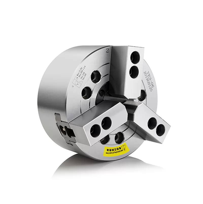
The chuck is a mechanical device on the machine tool for clamping the workpiece. A machine tool attachment that clamps and positions the workpiece using radial movement of the movable jaws that are all over the chuck body. The chuck is usually composed of a chuck body, a movable jaw and a claw drive mechanism. Chucks are typically mounted on lathes, cylindrical grinders and internal grinders, and can be used with milling machines for milling machines and drill presses.
When it comes to chucks, the most common contact is the manual three-jaw centering chuck on a conventional lathe (such as the CA6140). Take a look at its mechanical structure first.
Manual three-jaw centering chuck structure principle: Rotating the bevel gear with a volt wrench, the bevel gear drives the plane rectangular thread, and then drives the three-claw centripetal movement. Since the pitch of the square rectangular thread of the chuck is equal, the three-claw movement distance is equal. There is an automatic centering effect. In addition to this, the three claws can be disassembled to hold the relatively small bar. The centering accuracy depends on the accuracy of the chuck itself and the amount of jaw wear. Generally, we can adjust the centering accuracy by adding a spacer.
Classification of common chucks:
From the number of jaws of the chuck can be divided into: two-jaw chuck, three-jaw chuck, four-jaw chuck, six-jaw chuck and a specific chuck.
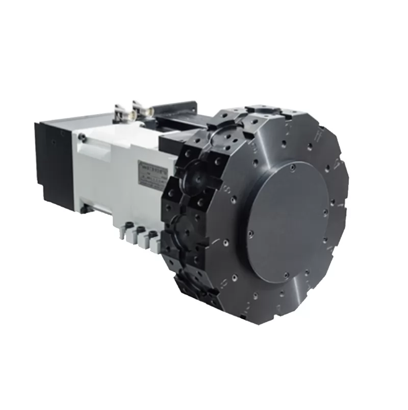
From the use of power can be divided into: manual chuck, pneumatic chuck, hydraulic chuck, electric chuck and mechanical chuck.
From the structure can be divided into: hollow chuck and medium real chuck.
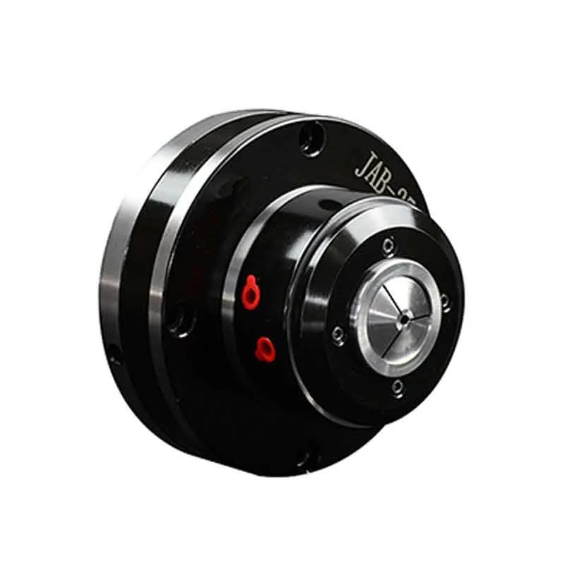
On the CNC machine tools, the most used one is the hydraulic chuck. The above pilot introduces the structure classification and working principle of the hydraulic chuck in the CNC machine.
Working principle: The action of the solenoid control through the PLC drives the action of the solenoid valve - the direction of movement of the hydraulic oil changes accordingly - the piston of the rotary cylinder is moved to the left and right - a wedge mechanism (or possibly a helical tooth) outside the card drive plate / Conical surface and other mechanisms) transform the shaft into motion to move - clamping the workpiece
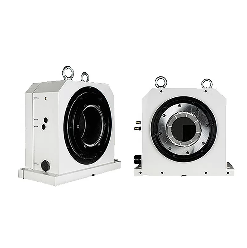
Hydraulic chuck can be divided into two structures.
One is that the front-mounted hydraulic chuck, that is, the chuck and the rotary cylinder are integrated, the installation is intuitive and convenient, and the price is economical and cheap.
One is a pull-back type hydraulic chuck, which is mounted on the rear end of the lathe spindle, and the rotary hydraulic cylinder is installed at the rear end of the lathe spindle. It is characterized by the chuck and the driving cylinder, and the ability to install waterproof anti-cutting fluid is very good. The manual machining machine uses this structure.
 CO.,LTD.")