Apr. 29, 2024
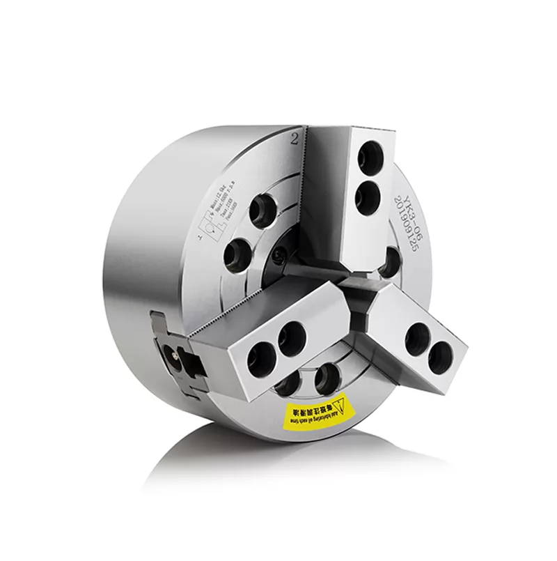
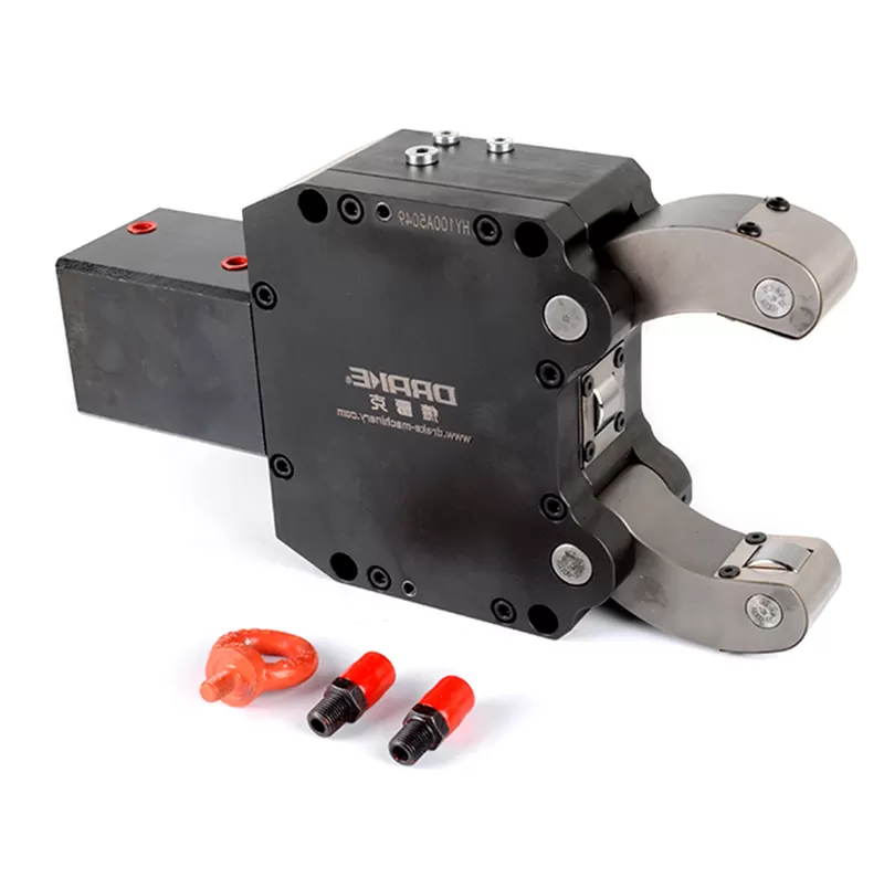
Many customers do not understand the installation and debugging process of the laser cutting chuck for machine pipes, and the cutting is so accurate that it cannot achieve the desired effect, and they doubt the accuracy of the chuck for the first time. I explain the whole debugging process for everyone by means of graphic presentation, please be sure to read it carefully.
Factors affecting cutting accuracy and solutions:

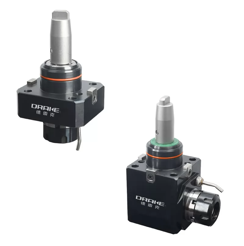
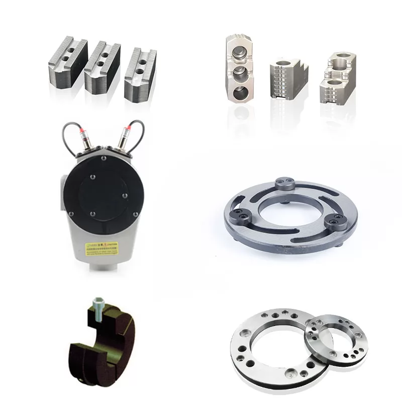
The chuck type uniformity is properly adjusted, DK4 type is within 0.1, MSS type is within 0.1, SD type is within 0.25, BK0 is within 2, and LK is within 0.05;
Fix the dial indicator on the dial bed, the bottom surface of the meter pointer chuck cylinder, the bottom surface of the lifting card body, detect the straightness, and adjust it in place, here is usually solved by padding copper; fix the dial indicator on the tip The card launches the side of the barge, and the front and rear jump card adjusts the positioning, detects the positioning degree, and is in place. Here, the adjustment and reception on the rotating seat is generally used to solve the problem.
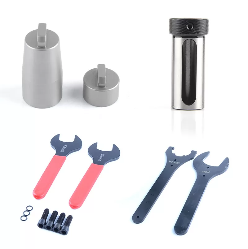
Fix the percentage meter or fix it on the surface of the rear chuck and clamp it with the rear chuck. The table indicates the plane where the front chuck is installed on the inner ring. Rotate the rear chuck to detect the points and adjust them in place (tips: detect quartiles), This is generally solved by padding copper skin and adjusting the top lock;

Fix the dial indicator on the rear chuck area or clamp it with the rear chuck, and rotate the rear chuck on the outer diameter or inner wall of the inner ring of the front chuck bearing of the front chuck. Tightly solve the problem of skin and adjustment.
The order is reversed to achieve the effect, in fact, it is even smaller.
Because the almost unused value will directly affect the processing, precision and straightness of the cutting machine, the other materials are almost all curved, so don’t be afraid of trouble or mentality.
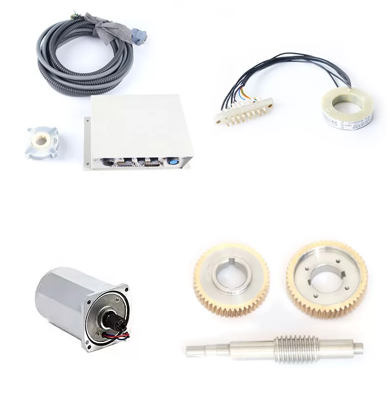
At that time we need to come for a re-inspection. Then the card is checked at the same time. , Fix the percentage meter on the head of the bed, fix the meter on the spot detection rod, the rear view changes, the parallelism between the concentric card and the horizontal direction of the machine tool and the guide rail; The parallelism between the concentric axis of the front and rear chuck and the vertical direction of the machine tool rail.
6.The front and rear chucks are checked at the same time, and the distance between the front and rear chucks is as wide as possible.
Fix the table with a few percent of the fixed table, and the indicator stick close to the card while rotating the card to detect the accurate positioning of the front and rear chuck respectively; grasp the inspection rod and rotate it to detect the repeated positioning of the front and rear chuck respectively.
We are a laser chuck manufacturer. If you are interested in our products, please contact us now!
 CO.,LTD.")